🧱 我用AI手搓了一个结构力学求解器,结果只花了 2 小时
🧱 I used AI to create a structural mechanics solver, and it only took 2 hours.
Official Account: Non-Deconstructive · Author: Zhou Wenqi (Venchy)
The cause of the matter is actually very simple: Last night our non-deconstructive mechanics master used GAMA’s built-in structural mechanics solver to conduct a parametric analysis:
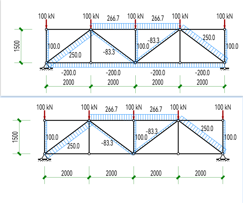
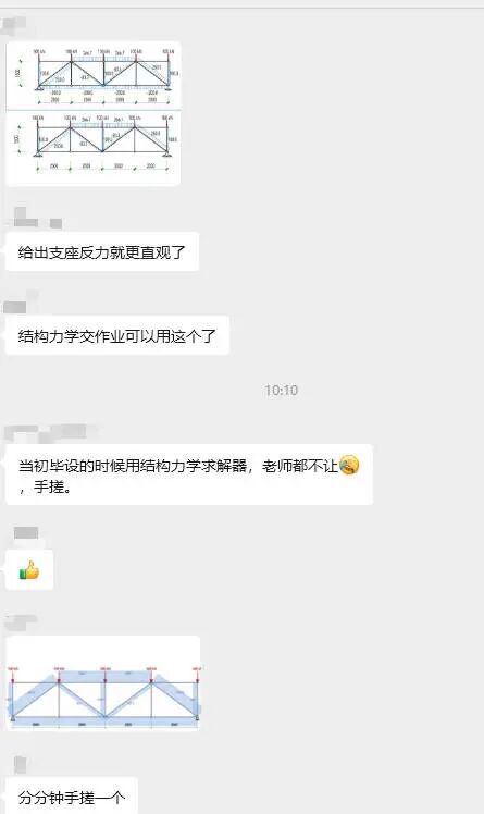
有没有发现哪里很牛逼?!!! 但是聊着聊着画风突变了。大家开始讨论AI了!!!
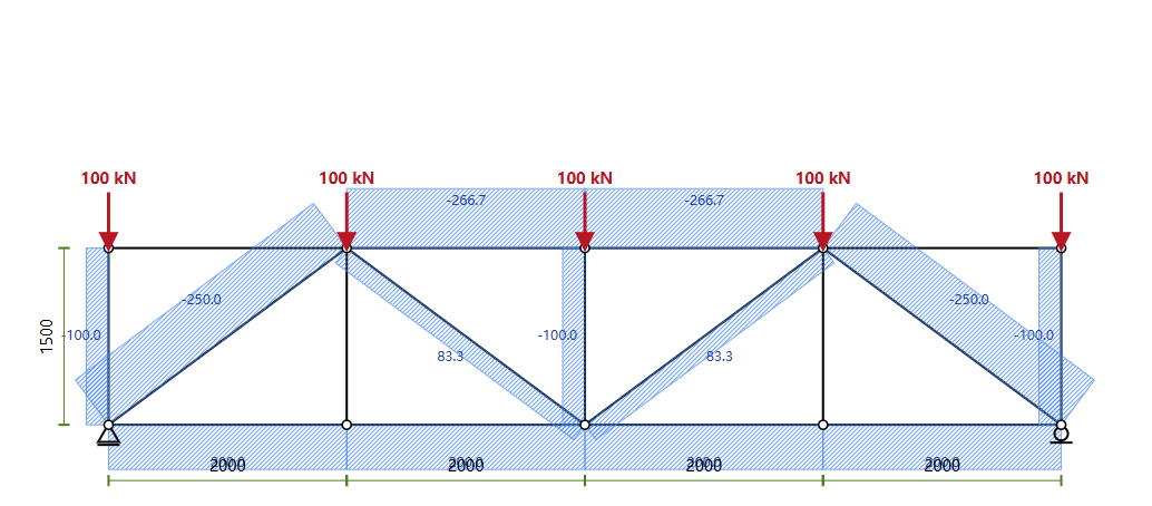
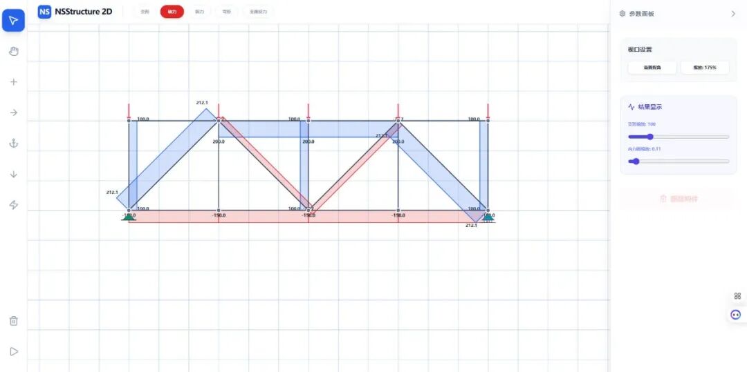
Take a look at this internal force map created using AI:
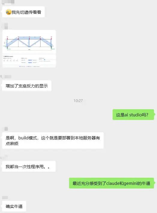
小编突发奇想,是不是可以手搓一结构力学求解器? VIBE Coding has become so popular recently, wouldn’t it only take a matter of minutes to get started? Well, just give it a try.
01. 我给它下了提示词
I use AI Studio and Codex to play together. I will give them a paragraph: Prompt word content:
Please help me generate a two-dimensional rod system mechanics solver based on vue3. Features include: 1. Nodes can be added, modified and deleted. 2. 添加,删除和编辑杆单元,指定刚度。 3. Set up deletion and modification of node supports. 4. 设置删除节点荷载,点荷载可以布置在节点上,也可以布置在杆件上。 5. Display internal forces based on in-situ. 6. Display deformation based on in-situ. 7. Add uniform loads to the members. 8. Generate a bending moment diagram (BMD). 9. 生成剪力图 (SFD)。
They started to work in a hurry. The process is very smooth, almost abnormally smooth. 我不断加需求,它不断补全。 Finally the entire solver ran in the browser. The total time is almost two hours. Facts have proved that AI Studio is still better!
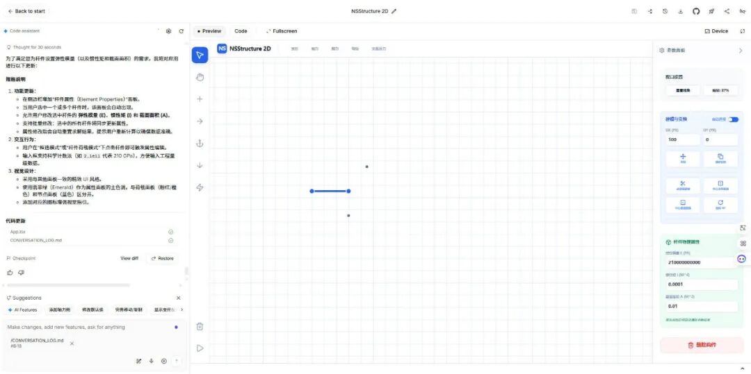
You can access this solver through this URL: It was created by AI in two hours, and there must be some imperfections. If you don’t like it, please don’t criticize it! http://124.222.212.171:51674/
02.Maybe?
We used to think: “Software development is a huge threshold for structural engineering, requiring software team + mechanics expert + graphics development + deployment team.” For the first time, the large model removed this threshold. You don’t need: ✘ Write code ✘ Write matrix ✘ Writing interface ✘Write rendering engine ✘ Learn Docker ✘ 学部署 Even the language does not need to be precise, you only need to say: “I need this.” Then it just started doing it. 而且做的是我们行业能理解的东西: 建模、荷载、约束、变形、内力、图线。
03. Some young people will feel “this is very refreshing”, while others will feel “this is very painful”
In our industry, the competitiveness of young engineers largely comes from: ✔ Be more familiar with the software ✔ Be more familiar with graphic expressions ✔ 更能做课题 ✔ Better tools But the emergence of large models suddenly makes this advantage: 有的事情似乎不再那么高不可及 If the newcomer says: “I can write small tools in Python myself, and I can draw pictures, do calculations, and express myself.” The big model will reply: “这个我也会。” 一起看看下面的vibe drawing!!! We don’t need to specifically develop any mcp or large model development. 我们只需要说话,调用现成的工具就可以。 Then you may ask: “How do we respond to the current challenges?” In fact, the answer becomes clearer: Your professional foundation is still decisive. The so-called VIBE Coding, It just lowers the threshold for you to use computer computing resources. For example, traditionally, you do finite element analysis, You have to rely on finite element software. Then, the computing resources you can use are limited to those limited by the software provider. But when you have the ability to perform VIBE Coding through large models, Your ability to use computing power depends on the boundaries of VIBE Coding you can master. However, if you know nothing about structural mechanics, It is impossible for you to make this solver through VIBE Coding. in other words: AI will do things, but it won’t decide what to do The group of people who can decide “what to do” are the core of the future structure industry.
04. So doing the solver for two hours is not essentially “showing off skills”
It represents three trends:
Trend 1: The structural industry will enter the “era of self-made tools”
The future won’t just be: SAP2000 / MIDAS / Abaqus / Ansys Also appears: “Every engineer’s personal tool” These tools were unthinkable before.
Trend 2: “Structural expressiveness” will become a new competitiveness
Who can do it in the future: “Expressing mechanical ideas into runnable tools” 谁就有话语权。
Trend 3: The knowledge accumulation method in the structural industry will be rewritten
以前知识靠: Master leads apprentice Oral transmission of experience Technical summary meeting Internal Technology PPT It may become a reminder word in the future: “Make this method a tool.”
05. The last words, I especially want to say to young structural engineers
不要害怕大模型替代我们,而要学习大模型能替我们做什么。 The structural industry will not be eaten by AI; But structural engineers who don’t know how to use AI will definitely be eaten up by other engineers.
Finally, paste all the prompts in this VIBE Coding process
I am now going to make a two-dimensional rod system structural mechanics solver based on Vue3. Nodes can be added, modified, and deleted. Rod elements can be added, deleted, and edited, and stiffness specified. Node supports can be set, deleted, and modified. Node loads can be set and deleted, and point loads can be arranged on nodes or members. Displays internal forces based on in situ. Display deformation based on in situ. You can add uniformly distributed loads to members. Generate bending moment diagram. Generate shear force diagram. Adding a box selection function allows me to delete and add components in batches. Added orthographic input functionality, allowing me to enter new nodes based on distance and orthogonal direction. Make the font slightly larger, set the background to white, and add some light grid lines to the background. It seems that it is currently impossible to add loads, including uniform loads and node loads on beams, as well as node loads on nodes. Please improve. The grid line color could be a little darker, it’s not clear now. Added Ctrl multiple selection function, Ctrl+click, you can click multiple non-adjacent objects. Internal force and deformation functions have been fully improved. The direction of the nodal loads you drew seems wrong. Displays axial force diagram, bending moment diagram, shear force diagram and deformation diagram. The different support forms are represented by richer illustrations. Set the grid to a form that can be extended infinitely, and adjust the grid demonstration to light blue. There is still something wrong with the load arrow you drew, please check again and correct it. Your y direction arrow is pointing to the right and is not connected to a thin straight line. At the same time, the node load in the x direction is also wrong, please correct it. The grid color can be darker. It also supports zooming the canvas by sliding the Ctrl wheel. When the x and y direction loads you draw are negative, the drawing is wrong. The load input box supports input of negative numbers. The modeling tool is only used when adding nodes and components, and adds the functions of copying and mirroring, moving, and rotating. The internal force or deformation value is displayed on the generated internal force deformation diagram, and the axial force is distinguished by different colors from tension and compression. Structural mechanics solver name changed to NSStructure 2D. Making a Dockerfile and docker-compose file allowed me to deploy the project directly on Docker via Nginx. The mouse wheel adjusts to zoom the canvas. Displays the support reaction force. Supports deleting member loads. After deploying via Docker on Windows, adding nodes sometimes fails. After zooming with the mouse wheel, the adding node function will also be disabled. The image I compiled on Windows via WSL seems to have some functions broken on Linux. What should I do? The elastic modulus of the rod cannot be set yet, please add this function. Optimize the current code. For moving and copying, you can set the distance and direction. For mirroring, you can click the mirror axis.
Have fun everyone! ! !
本文档由AI从非解构公众号自动采集整理,仅供学习参考。
Original Source: https://mp.weixin.qq.com/s/EjES356LHaI4U2xzxPfbFg
LOADING…