When an architect throws me a Rhino model—
When an architect throws me a Rhino model—
Official Account: Non-Deconstructive · Author: Zhou Wenqi (Venchy)
对于一般的常规项目而言,平立剖面图加上与建筑师适当的沟通,就足够作为结构模型建立的背景资料。但是当收到图1这样的建筑平面图提资的时候,小编的内心是懵逼的,这明明就是地形图么~深深的无力感~~~好歹来个三维的模型啊~~~ So, the architect gave me a Rhino model like Figure 2, but I still felt powerless. It was really just a small hill. How can I get such an enchanting shape with conventional ideas? ! It seems like you need to take an unconventional route and acquire unconventional skills~~~
STEP1 Rhino→CAD
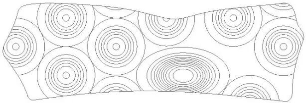
Figure 1
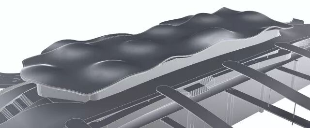
Figure 2 这么难想,索性就不想了,上个小网放松放松心情吧,说不定上着上着灵感就来了。。。灵感就来了。。。上网一不小心看到了下面这几张图,灵感就真的来了。
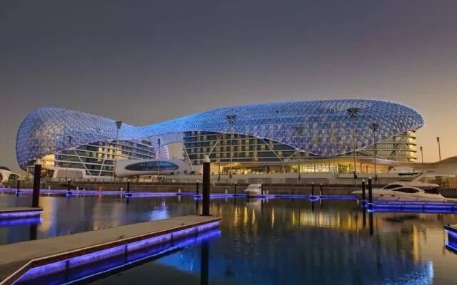
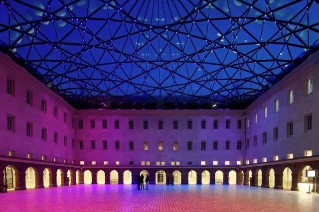
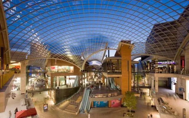
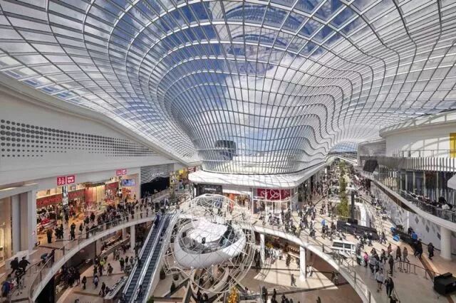
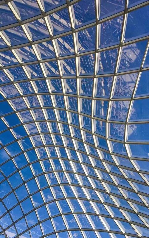
要么做个单层网壳?那根据建筑甩给我的这个Rhino模型可不行,怎么的也得给个线型网格的模型吧,建筑大大给的Rhino都是曲面啊,我的单层网壳都是杆件啊,建模都是要线单元的呀,我要的线呢?线呢?怎么从rhino里面搞出来单层网壳建模要的线呢?线搞出来了又要怎么算?!!
It is difficult to figure out, and you have to learn it even if you don’t know Rhino. It takes n many lines to draw on such a large plane. It is also very difficult for Rhino to draw so many lines. Is there any way to draw so many lines instantly? This time it was Du Niang who gave me the inspiration~ I think I can use Grasshopper~~~ Grasshopper (GH for short) is a plug-in that uses procedural algorithms to generate models running in the Rhino environment. It is currently the introductory software for parametric design in design professionals. The biggest feature of GH is that it can issue more advanced and complex logic modeling instructions to the computer, so that the computer can automatically generate model results based on the proposed algorithm. By writing modeling logic algorithms, mechanical repetitive operations can be replaced by computer loop operations; at the same time, designers can embed richer generative logic into the design model. Compared with the traditional working mode, both the modeling speed and level have been greatly improved. Just use it. Grasshopper can be regarded as a concept of parametric modeling. Although it is visual, it can also be regarded as programming~ I discussed it with architecture and it seems that I have some ideas. 第一步,在平面上划分网格 第二步,将平面上的网格投影至空间曲面 The third step is to modify the curve projected onto the surface into a straight line The fourth step is to select the obtained spatial grid and export it into a CAD file. 就这张折腾出了个Grasshopper的电池(图3),简单是简单吧,线型模型是搞出来了(图4,图5)~~~
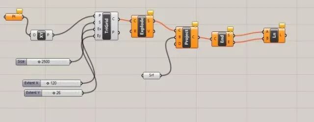
图3
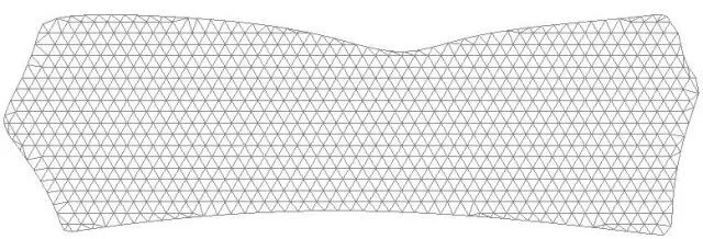
图4
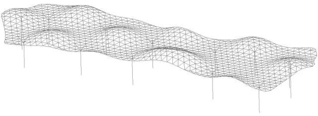
Figure 5
STEP2 CAD→SAP2000 The Rhino surface is converted into a CAD surface… So what software should be used for simulation? ! Sap2000? Midas gen? When considering several problems encountered during the analysis process, I resolutely chose Sap2000. The reason is very simple. SAP2000 can carry out secondary API development. One advantage of Sap2000 is that it is developed based on object-oriented technology and has an open interface. Users can not only construct and analyze using the graphical operating interface provided by the software, but can also connect its interface through programming for modeling and analysis. The advantage of the former is that it is very intuitive and suitable for small structures, while the latter is very effective for large structures and can reduce a lot of workload. Sap2000的API接口支持多种语言,包括VBA, VB, VC#, VC++,Fortran, Matlab。其中最为好用的莫过于VBA,因为VBA可以直接通过宏与Microsoft Word和Excel连接,而Excel中又提供了很多可以直接在单元格中操作的简易函数,将单元格、函数、VBA、SAP2000结合使用,可以实现用户的很多需求。相比之下,Visual Studio的开发方式下,显示数据和计算就没有Excel那样方便直观,想显示图形界面还要操作很多控件增加了工作量。Matlab的使用不像Excel那样普及,数据显示同样没有Excel直观。 The first problem is the live load loading of the lattice shell surface unit. 荷载规范规定的不上人屋面活荷载取值0.5kN/m2(投影荷载),要是面单元法向量和水平面垂直自然不用处理,但是这个曲面上的面单元法向量并不都垂直于水平面,所以施加的活荷载需要按照面单元投影面积与面单元实际面积的比值进行换算。 There are thousands of area units, do we need to process each area unit? ! The workload is still extremely huge, and it’s time to use the Sap2000 API as a killer. 其实这个程序的计算过程并不复杂(图6): 第一步,计算面单元的面积A1。 Read the nodes of each surface unit → calculate the side length of each surface unit based on the nodes of each surface unit → calculate the area of the surface unit based on the side length of the triangle 第二步,计算面单元的投影面积A2。 Read the nodes of each surface unit → Unify the z-axis coordinates of the nodes → Calculate the side length of each surface unit based on the same z-coordinate node → Calculate the projected area of the surface unit based on the side length of the triangle
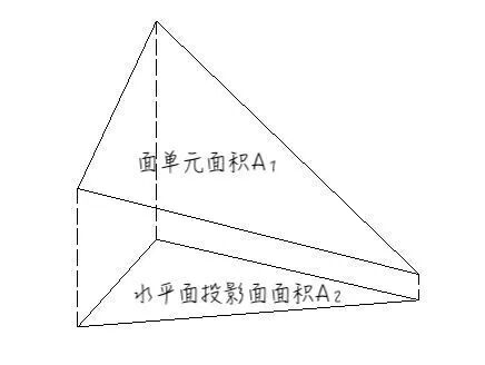
Figure 6 The third step is to calculate the area ratio, convert the live load, and assign it to each surface unit using the API function. With only very simple API operations and simple calculations, the process of applying live load is complete. The effect can be seen in Figure 7. The assigned live load value changes with the change of the roof curvature.
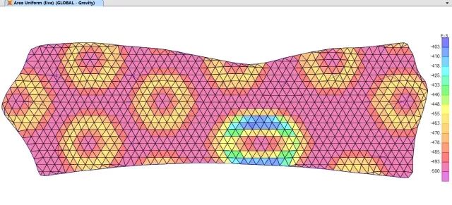
Figure 7 The second problem is the problem of the local coordinate axes of the reticulated shell line element. This surface is very free and unrestrained and does not follow the traditional single-layer lattice shell routine at all. Naturally, the components inside the reticulated shell cannot work according to the pressure components in the routine. Most of them are still bending members. Circular cross-sections do not seem to be so effective at this time, so rectangular cross-sections can only be used~ Then here comes the problem. It seems that the local coordinate axes of the line elements imported from CAD into Sap2000 do not meet our calculation requirements. In Sap2000, units such as points, lines, and surfaces have local coordinate systems, and three colors (red, green, and blue) are used to represent their local coordinates. Among them, red is the 1st axis, green is the 2nd axis, and blue is the 3rd axis. When importing the linear dxf file into Sap2000, the default 3-axis of the beam element is parallel to the horizontal plane. Just look at Figure 8 and you’ll understand!
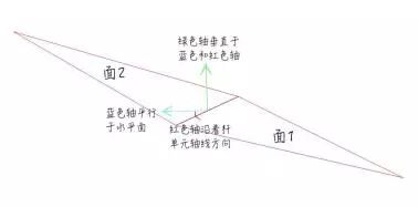
Figure 8 Look at Figure 9. The two axes of the rod change with the normal vector of the building skin surface. Otherwise, it would be ugly, and the connection nodes of the surface elements on both sides of the rod element would not be easy to make! Therefore, the local coordinate axis of the lattice shell member still needs to equally divide the angle between the two adjacent surfaces~
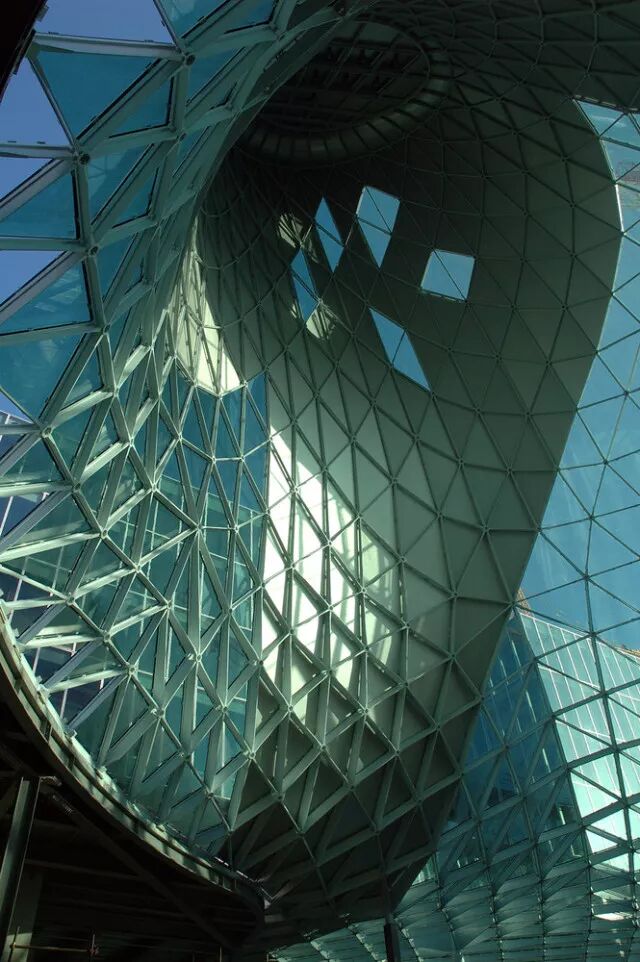
Figure 9 话虽如此,要把每根杆件要转动的角度计算出来,靠手算?有点像天方夜谭啊,还是数以千计的杆,还是数以千计的面,怎么算?同样的配方,同样的味道,Api吧。只是这次还得重新把我的高数书拿出来重新温习一遍。。。正所谓少壮不努力,老大学高数。什么向量了,什么右手定则了,统统重新学起来。。。
Figure 10 高数学完也没用,程序什么的还是要写起来的。为了写篇公众号整理个流程图,如图11。来看看成果(图12,图13)。
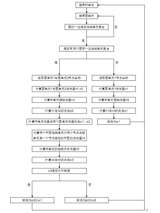
Figure 11
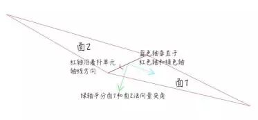
Figure 12
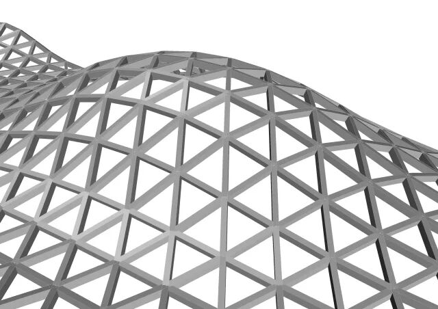
Figure 13 以上这两项工作做完,基本上告别繁重的体力劳动,想想可以愉悦地用Sap2000做分析吧。。。但是,还是太年轻了。用Sap2000做后屈曲分析?!呵呵哒!!!你咋用sap2000同时考虑材料+几何非线性?!塑性铰定义材料非线性?试着跑了一个,做到一半软件就罢工了~只能上高阶选手了。
STEP3 SAP2000→ABAQUS There are still many ABAQUS interfaces on the market, but unfortunately they are either charged or the effect does not meet the calculation requirements. I have tried many but they are not satisfactory (actually I am poor and cannot afford them). Just write one yourself in python. I hold a few official ABAQUS manuals and write them down, which can be considered a good harvest. 过程用一句话就能概括,就是把Sap2000的s2k文件转换成ABAQUS的inp文件。但是有几个特别要注意的点还是希望和大家分享。
- The local coordinate axis of the beam element cannot be defined in the cae interface and needs to be completed with the help of the inp file when submitting the inp file.
- Definition of quality. Some information says that the additional mass unit must be used to define additional mass in ABAQUS… Please, there is no other way… I personally summarized three ways to define quality: ①mass defines additional mass through points ABAQUS analysis user’s manual 30.1.1 ②density 通过密度定义质量ABAQUS analysis user‘s manual 21.2.1 ③Nonstructural mass defines mass through components and is divided into line elements, surface elements and solid elements with different definitions ABAQUS analysis user’s manual 2.7.1 3) To release constraints and define hinges, you need to use the *release keyword, which cannot be defined directly through the cae interface and needs to be operated in the inp file. The verification of the interface still needs to pass the periodic vibration shape. Figures 14 and 15 are the results of modal analysis of ABAQUS and sap2000 respectively, and the errors are not bad. Figures 16 to 22 show the first three modes of sap2000 and ABAQUS. The results are still consistent. I have learned Python for so many years…
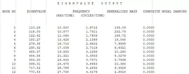
Figure 14
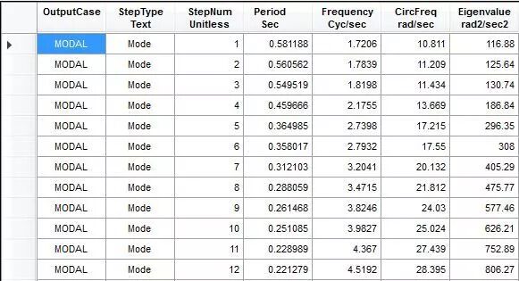
Figure 15
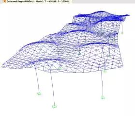
Figure 16
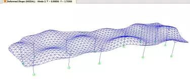
图17
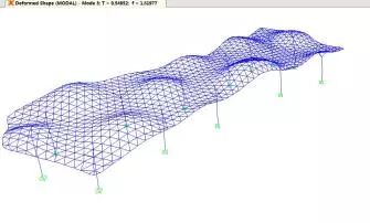
Figure 18
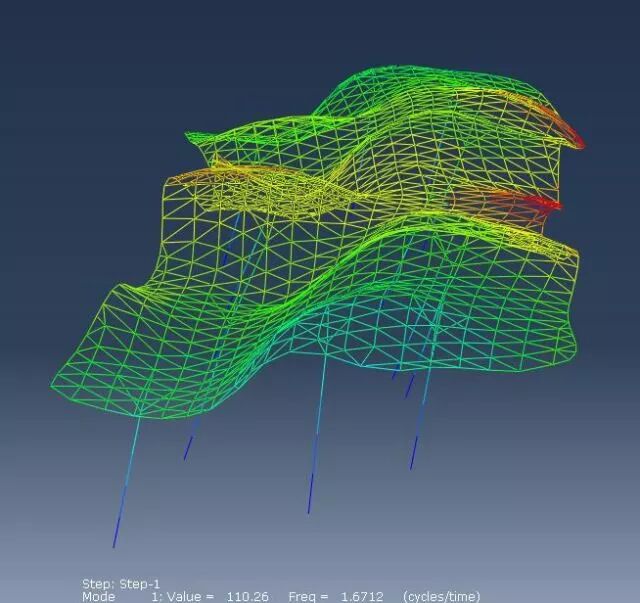
Figure 19
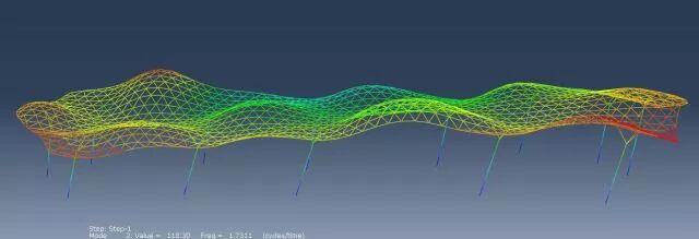
图20
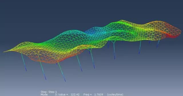
图21 You haven’t had enough of it yet, right? Party A’s father has started to whip up the drawing again, so he can only continue to draw pictures, so let’s stop here first.
Summarize Since I have no experience in similar projects, this project was quite complicated. I thought of various methods and started from scratch. Do you have some experience like this~ 1) Don’t just be addicted to YJK and PKPM and be unable to extricate yourself. Rhino, for example, is not just a patent for the architectural profession. 2) The problems encountered in this article apply Rhino parametric modeling, Sap2000 API technology and python programming technology. These methods can save a lot of workload when encountering simple repetitive tasks with extremely large workloads. 希望本文对诸位有所启发,不足之处,还请批评指正。
本文档由AI从非解构公众号自动采集整理,仅供学习参考。
LOADING…