自己打造Midas和YJK接口
自己打造Midas和YJK接口
Official Account: Non-Deconstructive · Author: Zhou Wenqi (Venchy)
好多天前,小编收到一个Rhino模型,希望通过YJK-GAMA把Rhino模型转入YJK,生成YJK模型。这个操作对YJK-GAMA来说简直是小菜一碟。
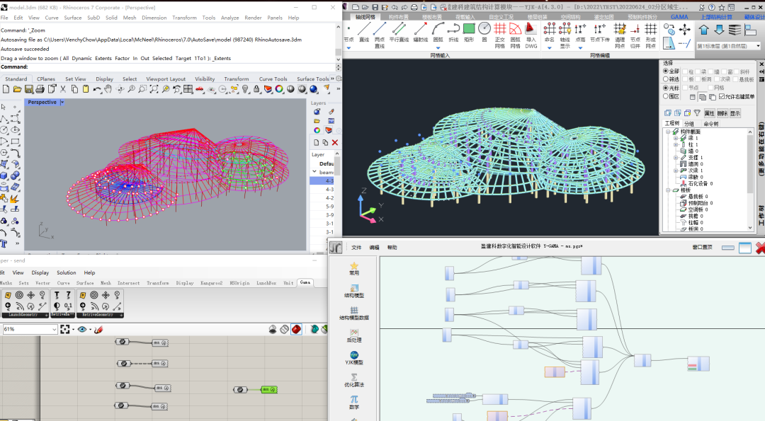
With the excellent interactive linkage capabilities and spatial structure model modeling capabilities of YJK-GAMA and Rhino, such a complex model can be built in seconds! I thought the delivery was over after the construction was completed. But the editor is still too naive: 这个模型已经有了一个Midas Gen的模型,如何将Midas模型转换为YJK模型呢?!
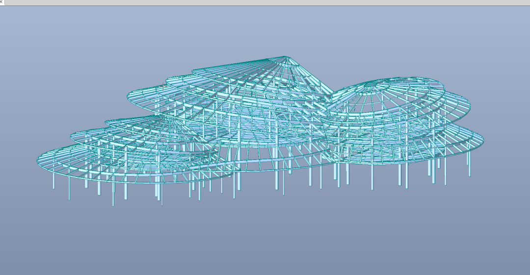
I have tried various Midas to YJK model conversion interfaces on the market. Because the models are too complex and prone to various errors, the converted models seem to be unable to be used directly. In fact, this problem is a piece of cake for YJK-GAMA. It just requires some DIY methods. Midas Gen can actually export structural model data. In order to build this model, we first need to export the node data, section data and component data in the model.
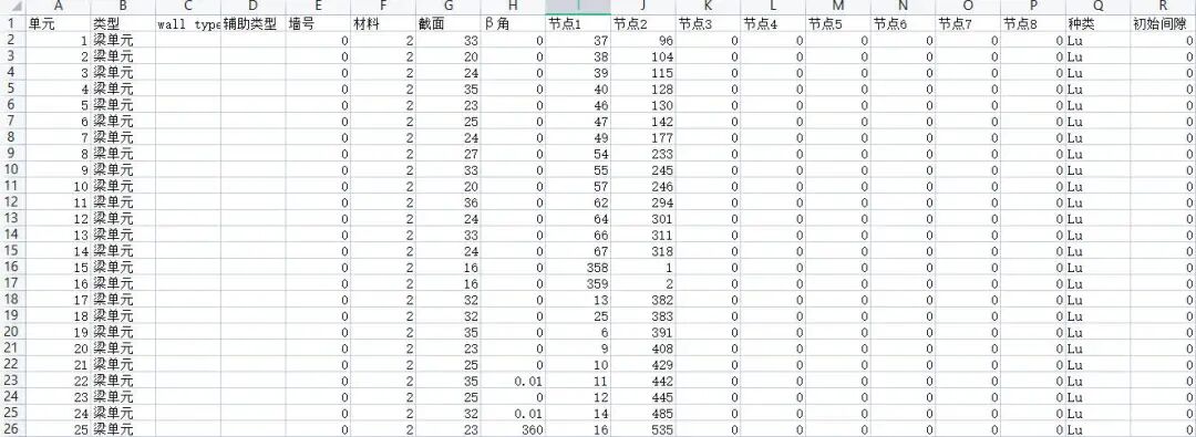
先说说思路 Let’s take a look at the data structure exported from Midas Gen: The node table contains the node ID and node coordinates; The section table contains all section IDs and related parameters in the model; The component table contains the component’s start and end point IDs, section IDs, corners and other information. In YJK-GAMA, we only need to simply create all the nodes and sections, and then build all the components easily based on the index IDs of the components’ nodes and sections.
Once your ideas are clear, you can start working. The starting point of this process is the model data exported by MIDAS Gen. We first export and store these data into an Excel file. Through YJK-GAMA’s “Read Excel” card, we can obtain all MIDAS model data and then operate on these data.
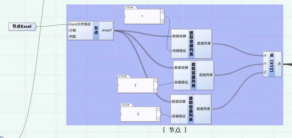
第一步 读取节点Excel中的数据 Columns 1, 2, 3, and 4 in the node Excel are the node ID, X-axis coordinate, Y-axis coordinate, and Z-axis coordinate respectively. We can obtain the corresponding node data by extracting the container list card and entering the corresponding container path (the starting point of the GAMA list is 0, so the path of the X coordinate is 1). Then through GAMA’s “Point (XYZ)” card, you can create all the points in the model.
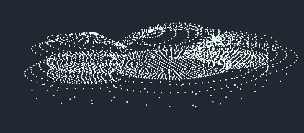
Step 2: Read component data and make line molds
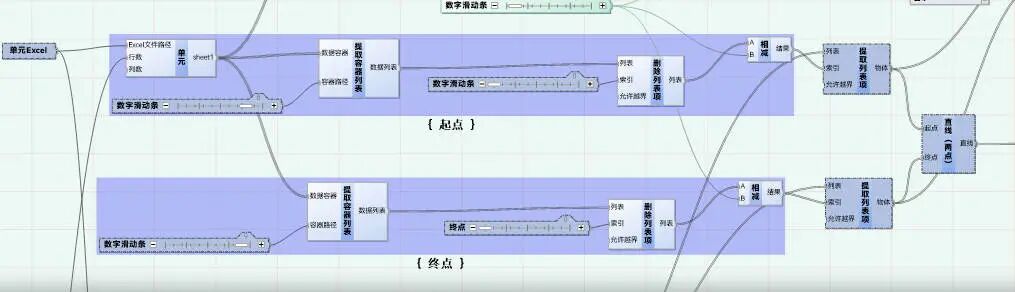
We then use the “Read Excel” card to read the model’s component data into GAMA. Since there are 3801 line units and the rest are area units, we only read 3801 rows in Excel. Columns 9-16 in the Excel table are the node numbers of the components. For line elements, we only need to read two nodes. Through some corresponding list operations, we can get the ID of the starting point and end point of the component, and then use the “Extract List Item” card to get the starting point and end point of the component in the node list using the ID of the node as the index. Then use the “Straight Line (Two Points)” card to create the line mold of the component.
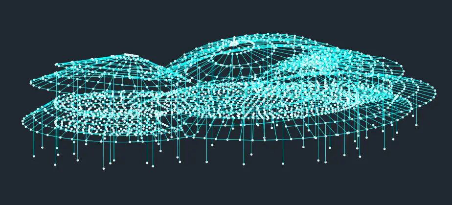
在建立完构件的线模后,我们需要根据柱子的向量,区分哪些构件是柱子,哪些构件是梁。这里主要根据构件的向量,通过逻辑判断卡片对梁柱进行分组。
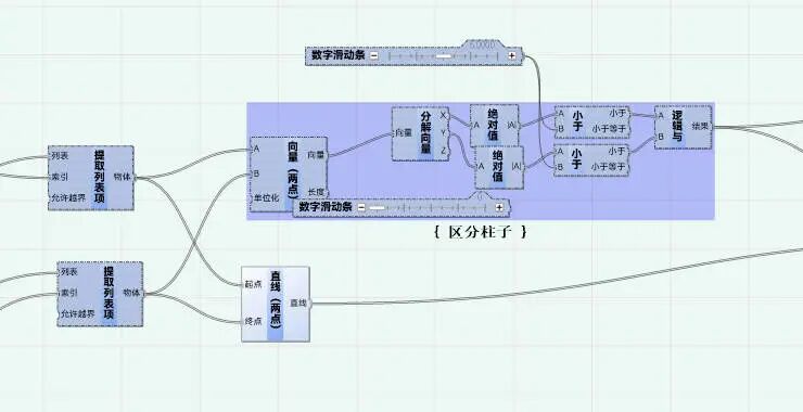
第三步 定义截面
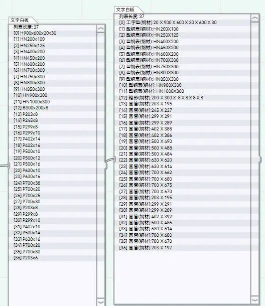
Similarly, through the “Read Excel” card, we can read the cross-section table of the model. According to this section table, we can make the corresponding section table through the frame section card in GAMA. The consistency of the section order must be ensured here, otherwise the defined sections will be wrong. 第四步 赋予截面 The read member table contains the ID of each section. We can obtain the sections in the section table based on the ID of the section and use the ID of the member section as an index, and assign it to the corresponding member.
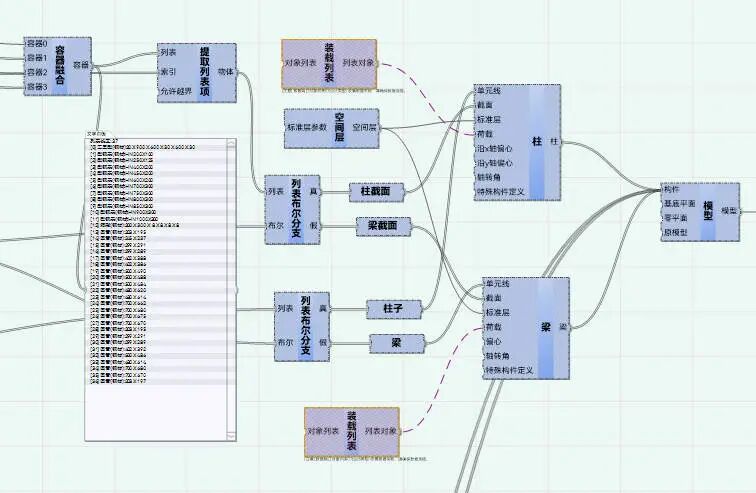
In this way, all member sections are defined. Step 5: Define skinning The data exported from Midas also includes data for area elements. We can construct the corresponding surface unit through the skin function in the upcoming YJK-GAMA1.6.
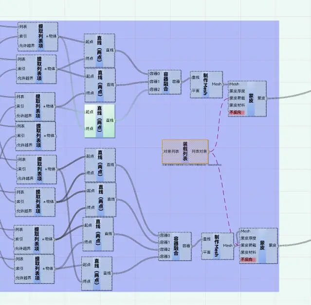
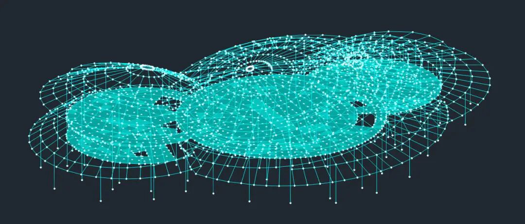
The surface unit data in Midas also contains the corresponding corner point ID. The corresponding node is also obtained through the corresponding corner point ID, and the edge of the corresponding surface unit is constructed. Create a Mesh through the edges, connect it to the skin, and then connect the skin to the model to achieve the construction of the corresponding skin. Step 6: Generate YJK model After completing the above operations, we can generate a YJK model by generating a YJK model card. The cross-sections of all components in the model are consistent with those in Midas. Skinning and plate elements in Midas are also consistent.
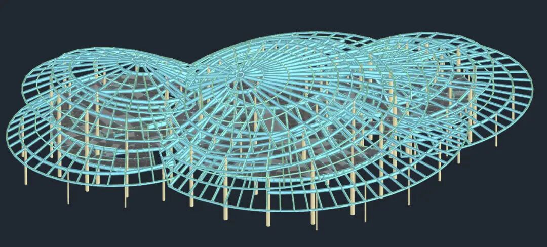
这样,我们自己DIY的YJK和Midas之间的接口就完成了。整个接口的制作过程,小编只用了半个小时,完全基于有限的几个GAMA卡片,可以说是非常简单迅速了。而且这个流程适用于各种各样的模型。另外,这个流程也可以反向通过Excel导出至Midas。各位有兴趣的小伙伴也可以尝试一下这个流程,说不定会有意外的惊喜哦!
案例文件的可以通过以下链接下载: https://pan.baidu.com/s/19nmVxGNeaN6nglu6peimsg Extraction code: 6ep7 YJK-GAMA现已升级到1.5版本 Join the QQ group and let’s explore together The infinite possibilities of YJK-GAMA!

联系我们“大菲儿”。 Join the “Digital Intelligent Design of Building Structures” WeChat exchange group, Let’s communicate and discuss cutting-edge technologies such as digitalization and intelligence Application in the architectural design industry.

We also welcome like-minded partners to join us. 一起来做点好玩的事情。

Next we will bring you more surprises, stay tuned Let’s go public!
*This document is automatically collected and organized by AI from non-deconstructed public accounts and is for learning reference only. *
Original Source: https://mp.weixin.qq.com/s/Gi_S1xjkB5aVm9urtlYCfA
LOADING…